What started all of this?

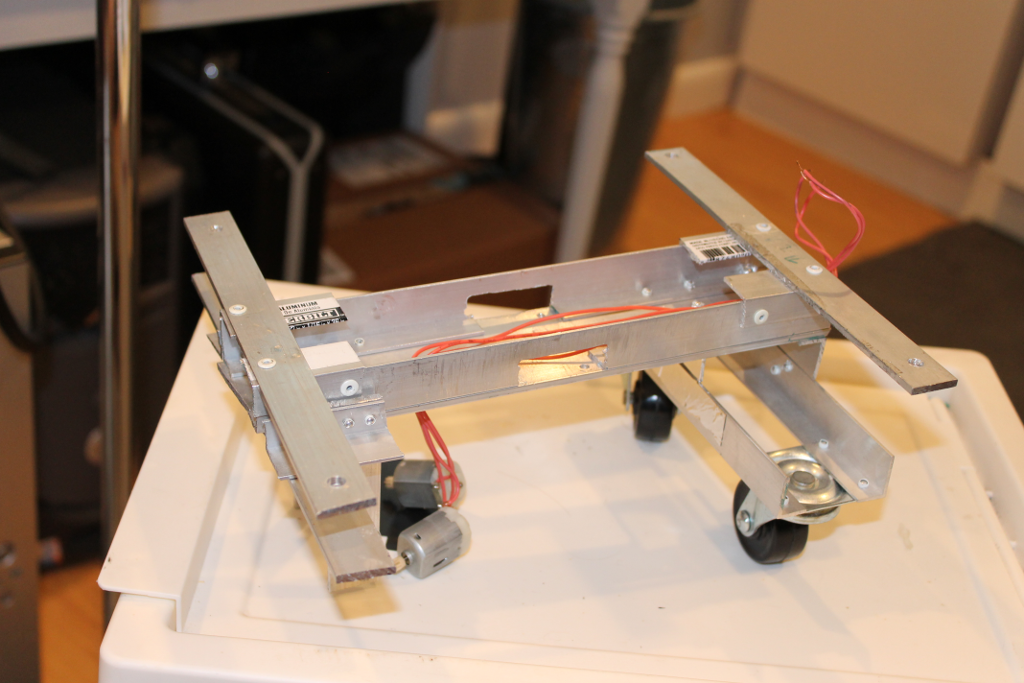
I must have come into the world with a screwdriver in my hand, since I have always loved seeing how things work and building new things. When I got to high school, I joined the Blair Robot Project, FIRST team 449. One of my experiences was using a pop riveter to make drive frames out of aluminum stock and laser-cut gusset plates. I wanted to build my own metal robot at home because riveting aluminum is so satisfying! My family already had a few hacksaws, tape measures, and drill bits, so I picked up a hand riveter and a center punch. Before long, I had a little frame together, almost ready to test. Now, I just needed some motors and a way to control them. I found some L293D chips and had my heart set on using a Raspberry Pi as a controller, using a 12-channel PWM Pi hat. Unfortunately, I wasn't familiar enough with network programming to write an application to control the Pi over a network live. So, my project went on hiatus for a few years.

Starter frame remains

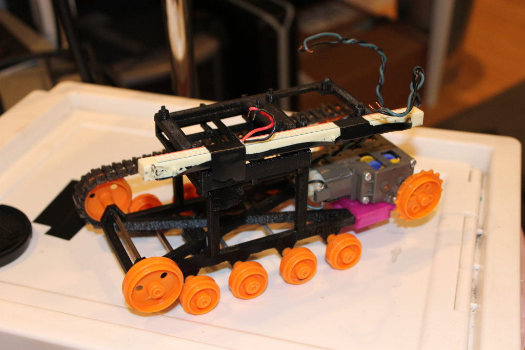
I have had to reuse some parts from the original frame, but some parts still remain.

Tracked frame rev 1

The remains of the 3D-printed tracked frame. I only had one set of control hardware, and it was on my wheeled robot at the time of documentation.

Return from hiatus

In fall 2019, I had the pleasure of working with a team to build a maze-mapping robot as part of Cornell's ECE 3400 class. Follow this link for my team's final site. Our robot could have worked better, though. Mainly, we started with a poor physical design which hurt our ability to test the robot. I wanted to continue a similar design on my own. So, I modified some of my group's code to work with my hardware (the frame pictured above). Two Arduinos would communicate wirelessly for control. My controller would be a single joystick. Soon into testing, it became clear that my old frame had a major flaw. Weight distribution and frame rigidity made it so that a drive wheel would often lose contact with the ground.

Without a quick way to fix that flaw, I decided to dig up some other old parts. I had a few Tamiya tracked vehicle kits that I wanted to make work. The challenge with those parts is that there is no built-in way to fit an Arduino on the kit's board. Solution: 3D-print some stand-offs to suspend a larger board above? I tried that, and it worked okay. However, I also found that the tracks did not stay on for long. So, I drew a new frame in OpenSCAD that was compatible with the axles and wheels that I already had and printed it. I then had a robot that kind of ran. I had made a small mistake nevertheless that led me to assume (incorrectly) that my motors drew too much current.

It Moves!

I knew that the wheeled motor-gearbox-wheel units did not have undesirable power characteristics, so I drew a simple frame that was compatible with those units. I also switched to a Feather M0 Express remote control as I could put a socket for an RF board on-unit and also have simple battery power and power management in the future. The power issues persisted. I realized that in the interest of safety, I was running 5V power through the Arduino's Vin pin, which requires approximately 6V to work well. As a result, even the small voltage drops from powering up the motors browned-out the ATMega. Supplying 5V to the 5V pin solved the problem. I just need to trust the USB power pack.

It Follows!

A classic sensing task for robots is to follow lines on the floor. From ECE 3400, I had experience getting a proportional-correction control loop to lead a robot along a line. I went a step further and added integral correction, and the robot runs much more smoothly than with proportional correction alone. It may be possible to add a derivative term to allow a more responsive robot, but for now, PI controlling works.

What is next?

The robot now has wall sensors and a servo to rotate them. In theory, it should now be able to stop itself from running into walls. I have not made any sort of exploration algorithm yet.

Wheeled frame with wall sensors

The robot is almost ready to see walls!